The idea is to use the Structure Sensor from Occipital (or an ordinary smartphone with SceneLib), to record the depths and colors of some scene, with readings of the accelerometers and gravitometers, etc. recorded, along with video with sound and color. Then using the orientation of the camera on those frames, given what should be the up direction, and the depths values to calculate a flat surface ahead and keep it relatively planted with the accelerometer and depth data, a "device" (perhaps made in a modelling program with bump mapping and specular highlights, etc, to make it realistic, and very detailed, and animated) is drawn on top with a timer displayed. It's supposed to look very technological. Perhaps it's plugged in by cables, like an external hard drive, but with changes. This is really a prank or just-for-fun project to see how far it can go, but it can be applied to film-making and reused for lots of different things. The data would be recorded and exported to computer where the heavy work would be done.
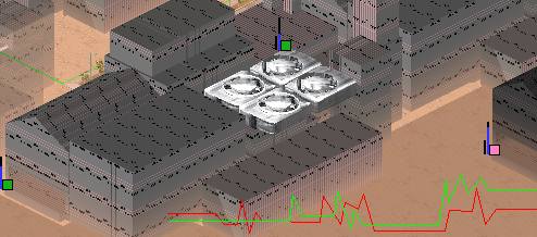
I have an image with some ventilation fan animations I made. The animation isn't there, but you can see sort of what I meant. If to put this on top a large external hard drive, to make it seem as if it's technical. And to make an LED numerical reader on top of it (I will explain what for).
So there would need to be an LED numerical display. The digits will count up slowly, to indicate how "G's" the device is producing, up to Earth's 1 G, and higher. As it does so, using the background (let's say it's got a TV right up close behind it and you can hear it playing and see it, with the device overlaid on top of it, and the camera moving around and shaking and panning etc. and maybe a finger moving closer) the device is overlaid on top using it's on depth values, to write into the depth of the scene, so that if there's something in front, it will discard the correct pixels based on depth.
What does the device do? It is like a gravitational amplifier, or space warper. As it increases the G's, the pixels will be altered using an effect similar to orientability maps. Basically, depending on the depths, giving the 3-dimensional positions of the scene surface vertices, and the colors there, a gravitational lensing effect would be created, like experienced near a black hole. I have a theory that the brain is innately built with such an understanding of the nature of gravity, or perhaps there would at least be a gut feeling of what this is. There can also be sounds added of a device powering up, whizzing up, etc.
A lot of other effects can also be made on this principle. Although that is the coolest one I wanted to make. You can also use the "spherical blending" method in "isometric shooters" to render fire, fog, smoke, explosions, clouds, etc. You can film a doorway with the door open, and you going through it, and use those depth and color values of you walking through, on top of a doorway scene with the door closer, to make it seem as if you've walked right through the door. Or film something in the kitchen or bathroom. Let's say the toilet. And another scene overlaid on top of it with your hand reaching in, to give the appearance of your hand going through the side and through the solid and appearing inside.
You can also make a video of yourself with an "alien" in your living room, giving it a handshake, etc (using motion tracking algorithms to track your hand pixels eg). You can make an app with some models of some celebrities, for smartphone perhaps using SceneLib, so that people can take photos of themselves with the camera view overlaid with a celebrity standing beside, animated, giving you a handshake, with your arm over their shoulder, or you in front of them and then behind, etc. You can film yourself with Arnold Schwarzenneger, Anna Kournikova, Pamela Anderson, Robert DeNiro, etc.
A more interesting thing can be done with plenoptic cameras from Lytro, using the 5-point algorithm or SceneLib perhaps. Because the Structure Sensor only has a range of 3.5 m, you can use plenoptic cameras (in theory) to film eg a skyscraper from another window, or from the ground, and eg make an alien UFO go in between the buildings, or fog, or explosions, etc.
There is an app called Unity-chan on iPhone, which is basically an anime girl 3D model with animations, for augmented reality (AR), that is rendered with the right orientation given the smartphone's accelerometers or gravitometers. Although it doesn't use depth-writing and depth-checking to make the girl appear correctly with anything overlaid on top, it does look interesting with things standing behind it.
Here is me playing around with it:


Also another effect I thought of... being in a space station, perhaps with feet braces to explain why you're not floating, and testing some device, with the walls etc made in a 3D modelling program.
So when I got the Structure Sensor and realized it was only 3.5 m ranged, I tried to come up with my own algorithms using only mono-RGB video. It's possible if you look for algorithms like "mono-SLAM" on Google. I wanted to use it to scan neighborhoods for use as levels in my shooter game. This is probably something somebody should look into, if it isn't already, using the techniques we have, to do urban scene reconstruction. Engineers and other companies use "remote sensing" with giant back-pack sized laser sensors to scan surroundings. But these are expensive and bulky.
So there's the 5-point algorithm. Originally I didn't realize what this was. I thought it was possible only with 3 points, to determine the relative orientation and translation of a camera frame, with respect to the previous camera frame, using the tracked positions of pixels shifted on the screen, using 3 (or rather 5) of them to derive all the needed information to get the camera angle, and the positions of all the points. I only realized 5 are needed when I laid it out in equations and found that 5 points are needed to solve and eliminate for all the variables.
It's been solved using Gauss's method using matrices (eg here in OpenCV https://github.com/opencv/opencv/blob/master/modules/calib3d/src/five-point.cpp ). But the way I laid it out before I found that, and which seems better to me even now, because it doesn't use matrices, doesn't use the double-sized floating point coefficients there in part of the solution, and because it just uses simple trigonometry and linear algebra, is to use basic algebra instead of matrices. And therefore should me more efficient, accurate, and precise, and give you an understanding how it works (because I don't understand the Gauss method with matrices).
I haven't finished solving it, but it's possible, and I might come back to it later. The reason I didn't finish it is because it gets HUGE (over a 100 pages and growing fast) just for a single equation, solving for and isolating variables at each step, to combine them from two subsequent equations, and bring them together by substituting the solution for the isolated variable from one equation into that variable for the other equation, and simplify them. I did use wxMaxima to simplify this, but I found I needed the Reduce computer algebra system to use data files from text, using batch scripts, and to output to text files, for the next stage, to automate the process. I just didn't finish that, but I believe I did try it out. WxMaxima and pretty much any other CAS besides Reduce just dies under such huge equations, not only because it has to render them (Reduce can work in command line mode and in a mode to display the equations on a continuous line, instead of formatting to appear as if it's spaced out using several lines and rearrangement), but also because of memory constraints of any underlying Lisp interpreter (Reduce uses Portable Standard Lisp, unlike Maxima's and other's Common Standard Lisp, so doesn't have a fixed memory limit, or maybe it does but it can be changed, or maybe that's what I tried to do in the first place before I found Reduce, if I remember correctly), and just being too slow. You can probably get much better results if automating using a professional expensive CAS like Maple or Mathcad or Mathematica, the ones used in universities and engineering and science.
You can see here my attempts to first solve it on paper:


The exact equations are (recalling from memory):
a = point 1 screen x in frame 1
b = point 1 screen y in frame 1
c = point 2 screen x in frame 1
d = point 2 screen y in frame 1
e = point 3 screen x in frame 1
f = point 3 screen y in frame 1
g = point 4 screen x in frame 1
h = point 4 screen y in frame 1
i = point 5 screen x in frame 1
j = point 5 screen y in frame 1
k = point 1 screen x in frame 2
l = point 1 screen y in frame 2
m = point 2 screen x in frame 2
n = point 2 screen y in frame 2
o = point 3 screen x in frame 2
p = point 3 screen y in frame 2
q = point 4 screen x in frame 2
r = point 4 screen y in frame 2
s = point 5 screen x in frame 2
t = point 5 screen y in frame 2
The points must be in the range (-1,+1) of the screen's space, with eg up being +1 and right +1, for my implementation of these equations.
u = screen field of view angle horizontally
v = screen field of view angle vertically
w = camera frame 2 offset from 1 relative x position coordinate
x = camera frame 2 offset from 1 relative y position coordinate
y = camera frame 2 offset from 1 relative z position coordinate
z = camera frame 2 view vector x coordinate of total length 1, with frame 1's being vector (0,0,1)
A = camera frame 2 view vector y coordinate of total length 1, with frame 1's being vector (0,0,1)
B = camera frame 2 view vector z coordinate of total length 1, with frame 1's being vector (0,0,1)
C = camera frame 2 right vector x coordinate of total length 1, with frame 1's being vector (1,0,0)
D = camera frame 2 right vector y coordinate of total length 1, with frame 1's being vector (1,0,0)
E = camera frame 2 right vector z coordinate of total length 1, with frame 1's being vector (1,0,0)
F = camera frame 2 up vector x coordinate of total length 1, with frame 1's being vector (0,1,0)
G = camera frame 2 up vector y coordinate of total length 1, with frame 1's being vector (0,1,0)
H = camera frame 2 up vector z coordinate of total length 1, with frame 1's being vector (0,1,0)
By the way, whenever you solve for and simplify a solution for a variable in the main equation, you have to substitute that in ALL the other equations. The way I did it was, I kept track of all the other previous variables that I solved for and substituted, and the order in which I substituted them, that I then do the same on all the second main equations I use, before combining with the first main one (by solving for another variable in one, and substituting that variable in the other with the solution of the variable using all the other remaining variables).
I = ray right ratio of total length 1, for ray from camera frame 2 to point 1, for the right component
J = ray up ratio of total length 1, for ray from camera frame 2 to point 1, for the up component
K = ray forward ratio of total length 1, for ray from camera frame 2 to point 1, for the forward component
L = ray scaling ratio, to get the length distance of point 1 from camera frame 2 position, for the unit-length ray
M = ray right ratio of total length 1, for ray from camera frame 2 to point 2, for the right component
N = ray up ratio of total length 1, for ray from camera frame 2 to point 2, for the up component
O = ray forward ratio of total length 1, for ray from camera frame 2 to point 2, for the forward component
P = ray scaling ratio, to get the length distance of point 2 from camera frame 2 position, for the unit-length ray
Q = ray right ratio of total length 1, for ray from camera frame 2 to point 3, for the right component
R = ray up ratio of total length 1, for ray from camera frame 2 to point 3, for the up component
S = ray forward ratio of total length 1, for ray from camera frame 2 to point 3, for the forward component
T = ray scaling ratio, to get the length distance of point 3 from camera frame 2 position, for the unit-length ray
U = ray right ratio of total length 1, for ray from camera frame 2 to point 4, for the right component
V = ray up ratio of total length 1, for ray from camera frame 2 to point 4, for the up component
W = ray forward ratio of total length 1, for ray from camera frame 2 to point 4, for the forward component
X = ray scaling ratio, to get the length distance of point 4 from camera frame 2 position, for the unit-length ray
Y = ray right ratio of total length 1, for ray from camera frame 2 to point 4, for the right component
Z = ray up ratio of total length 1, for ray from camera frame 2 to point 4, for the up component
I" = ray forward ratio of total length 1, for ray from camera frame 2 to point 4, for the forward component
I~ = ray scaling ratio, to get the length distance of point 4 from camera frame 2 position, for the unit-length ray
I' = ray right ratio of total length 1, for ray from camera frame 2 to point 5, for the right component
Iz = ray up ratio of total length 1, for ray from camera frame 2 to point 5, for the up component
I| = ray forward ratio of total length 1, for ray from camera frame 2 to point 5, for the forward component
IGBP = ray scaling ratio, to get the length distance of point 5 from camera frame 2 position, for the unit-length ray
Now, assuming that camera frame 1 is at (0,0,0) in our relative coordinate system:
0 + I+- * Iu = w + (C * I + F * J + z * K) * L
0 + I2 * Iu = x + (D * I + G * J + A * K) * L
0 + I3 * Iu = y + (E * I + H * J + B * K) * L
0 + I? * I" = w + (C * Q + F * R + z * S) * T
0 + I. * I" = x + (D * Q + G * R + A * S) * T
0 + I, * I" = y + (E * Q + H * R + B * S) * T
0 + I 3/4 * If = w + (C * U + F * V + z * W) * X
0 + I? * If = x + (D * U + G * V + A * W) * X
0 + I' * If = y + (E * U + H * V + B * W) * X
0 + I+ * D? = w + (C * Y + F * Z + z * I") * I~
0 + I^ * D? = x + (D * Y + G * Z + A * I") * I~
0 + D- * D? = y + (E * Y + H * Z + B * I") * I~
0 + DS * D" = w + (C * I' + F * Iz + z * I|) * IGBP
0 + D' * D" = x + (D * I' + G * Iz + A * I|) * IGBP
0 + D' * D" = y + (E * I' + H * Iz + B * I|) * IGBP
Where:
I+- = in frame 1, with total length 1, the ray right ratio, for ray from camera 1 to point 1, assuming that the frame 1 right direction is aligned with +x axis
I2 = in frame 1, with total length 1, the ray up ratio, for ray from camera 1 to point 1, assuming that the frame 1 up direction is aligned with +y axis
I3 = in frame 1, with total length 1, the ray forward ratio, for ray from camera 1 to point 1, assuming that the frame 1 forward direction is aligned with +z axis
Iu = in frame 1, the length scale of the ray, from camera 1 to point 1, to give the correct distance to the point
I? = in frame 1, with total length 1, the ray right ratio, for ray from camera 1 to point 2, assuming that the frame 1 right direction is aligned with +x axis
I. = in frame 1, with total length 1, the ray up ratio, for ray from camera 1 to point 2, assuming that the frame 1 up direction is aligned with +y axis
I, = in frame 1, with total length 1, the ray forward ratio, for ray from camera 1 to point 2, assuming that the frame 1 forward direction is aligned with +z axis
I" = in frame 1, the length scale of the ray, from camera 1 to point 2, to give the correct distance to the point
I 3/4 = in frame 1, with total length 1, the ray right ratio, for ray from camera 1 to point 3, assuming that the frame 1 right direction is aligned with +x axis
I? = in frame 1, with total length 1, the ray up ratio, for ray from camera 1 to point 3, assuming that the frame 1 up direction is aligned with +y axis
I' = in frame 1, with total length 1, the ray forward ratio, for ray from camera 1 to point 3, assuming that the frame 1 forward direction is aligned with +z axis
If = in frame 1, the length scale of the ray, from camera 1 to point 3, to give the correct distance to the point
I+ = in frame 1, with total length 1, the ray right ratio, for ray from camera 1 to point 4, assuming that the frame 1 right direction is aligned with +x axis
I^ = in frame 1, with total length 1, the ray up ratio, for ray from camera 1 to point 4, assuming that the frame 1 up direction is aligned with +y axis
D- = in frame 1, with total length 1, the ray forward ratio, for ray from camera 1 to point 4, assuming that the frame 1 forward direction is aligned with +z axis
D? = in frame 1, the length scale of the ray, from camera 1 to point 4, to give the correct distance to the point
DS = in frame 1, with total length 1, the ray right ratio, for ray from camera 1 to point 5, assuming that the frame 1 right direction is aligned with +x axis
D' = in frame 1, with total length 1, the ray up ratio, for ray from camera 1 to point 5, assuming that the frame 1 up direction is aligned with +y axis
D' = in frame 1, with total length 1, the ray forward ratio, for ray from camera 1 to point 5, assuming that the frame 1 forward direction is aligned with +z axis
D" = in frame 1, the length scale of the ray, from camera 1 to point 5, to give the correct distance to the point
The line segments are expressed in this way with vectors:
line 1 in frame 1 = (0,0,0) to (0 + I+- * Iu, 0 + I2 * Iu, 0 + I3 * Iu) etc...
line 1 in frame 2 = (w,x,y) to (w + (C * I + F * J + z * K) * L, x + (D * I + G * J + A * K) * L, y + (E * I + H * J + B * K) * L) etc...
So:
(0 + I+- * Iu, 0 + I2 * Iu, 0 + I3 * Iu) = (w + (C * I + F * J + z * K) * L, x + (D * I + G * J + A * K) * L, y + (E * I + H * J + B * K) * L)
Note: I'm making all these single-character variables, because you need to have only a single, unique character in these CAS and can't use more than one, and it also makes the equations a lot shorter, than they would otherwise have been.
Given these identities for the camera's directional vectors, because they are perpendicular, so should have a dot product of 0, and are all of unit length, and can be obtained from each other using cross products of the other two:
F = D * B - E * A
G = E * z - C * B
H = C * A - D * z
C = A * H - B * G
D = B * F - z * H
E = z * G - A * F
I don't remember if you need all of these, but it will be easy to see, which variables you need, and which ones are left.
These are hard to understand, but they make sense if you take apart a dot or a cross product, and decompose them into the x, y, or z component, so see for yourself and make this yourself instead of just following my exact equations, probably.
Whenever you have a square root in the results, you have to split the further equation paths into a positive and negative square, and when at the end to check using the forward equation if it makes sense. There are only about 4 such square roots if I remember correctly and they were not a big problem.
F^2 + G^2 + H^2 = 1
C^2 + D^2 + E^2 = 1
A^2 + B^2 + C^2 = 1
I^2 + J^2 + K^2 = 1
M^2 + N^2 + O^2 = 1
Q^2 + R^2 + S^2 = 1
You won't use all of the above, because you can solve the others using the other identities.
C = E * B - D * A = - (E * z * B + D * z * A) / (z)
z = G * E - H * D
A = H * C - F * E
B = F * D - G * C
C = A * (C * A - D * z) - B * (E * z - C * B)
E = z * (E * z - C * B) - A * (D * B - E * A)
Assuming:
(I.e., the ratios for distance of the points are positive, so in front, of camera 1.)
Iu > 0
I" > 0
If > 0
D? > 0
D" > 0
And the same for camera 2?
L > 0
T > 0
X > 0
I~ > 0
IGBP > 0
These last ones are more complex:
The angle between three points, in both frame 1 and frame 2, will have a certain single angle, for any three set of these points.
And the horizontal and vertical angles of the fields of view, can be used also with the angles formed with camera 1 or 2, with any of the points, with respect to the near-plane, or near-arc.
The given variables are:
We have I, J, Q, R, U, V, Y, Z, I', Iz (the screen ratios of the points in frame 2, to give the ratios of the up and right vector along the near-arc, so called because the result will be at unit-distance from the camera's position), and the K, S, W, I", I| can be obtained from the previous ratios, because these are the forward ratios, and together they give a unit-length, and the screen 1 up and right ratios I+-, I2, I?, I., I 3/4 , I?, I+, I^, DS, D', and the forward ratios from them, I3, I,, I', D-, D'.
The following variables can solved or obtained and substituted in the order:
F, G, H (starting up vector for camera 2, of unit-length), C and E (the camera 2 right vector components, for x and z, which can be obtained solely from those of the up vector), A (the camera 2 view y, which can be obtained simply from the previous ones),
Iu, I", If, D?, D" (the lengths for the distances to the points from frame 1 [correction]),
Then the lengths of the points from frame 1, then the camera 2 translation x and y, etc...
You can solve the much simpler 2-dimensional equations to see a possible result. I also did not solve those, but I did start, and I think they only require 4 points, if I'm not mistaken.
I have at least two more really interesting topics, then maybe some others, maybe tomorrow. And some other minor ones.
Hope you enjoyed that. Now if you excuse me, I'm going to relax, because I have a thrashing headache, from inadequate sleep.
You can probably do all sorts of effects you want, eg refraction, lasers, or make games that used augmented reality, like a playing board that might be shared between two smartphones, with virtual figures that you look over by moving yourself and your smartphone around, and control on the screen.
[Edit] also I'm not sure if it's a good idea to use the variable name "i" because CAS may mistake it for the imaginary number constant.